At present, the urban rail aluminum alloy body adopts many aluminum alloy honeycomb profiles, and various profiles of different sections are formed by machining and welding to form the entire vehicle body load-bearing structure, and these profiles are load-bearing beams of the vehicle body structure.
Profile processing is the first process in the car body manufacturing process. The processed profile workpieces grow, the processing volume is large, the processing time is long, and ultra-large processing equipment is needed. Therefore, profile processing is often the bottleneck in the production process of the car body. Studying the profile processing technology to solve the difficult problems of profile processing is of great significance for ensuring the quality of profile processing, avoiding unnecessary losses and improving production efficiency.
1. Difficulties in profile processing
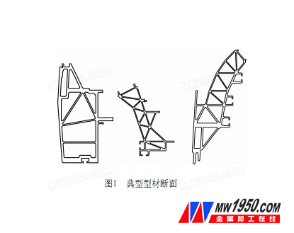
A cross-sectional view of several typical profiles is shown in Figure 1. The length of the profile is generally the same as that of the car body, generally 19 to 22 m. The wall thickness of a single rib is generally 3 to 2.5 mm, so the rigidity is small, the distortion is large in the range of the length, the bending deformation is large, the clamping is difficult, and the vibration during processing is large, so that the milling is extremely easy, resulting in unqualified product quality or even scrapped. There are two main difficulties in the processing technology of aluminum alloy car body profiles: one is how to design reasonable tooling and reasonable arrangement; the second is how to solve the processing of single thin-walled ribs.
2. Tooling design and layout
Different from general small parts milling, the common machine vise or pressure plate is used. The side beam and the top side beam type A are 22m long, the B type car is also 19m, and the air conditioning support beam is generally more than 4m in length. In addition to large processing equipment, special tooling must be designed to be fixed.
The key to tooling design is the determination of the processing station and the reference of the workpiece and tooling. In order to reduce the number of clamping and ensure the processing accuracy and efficiency, the number of times the workpiece is clamped must be as small as possible. Generally, the side beam and the top side beam are two stations. The selection of these two stations can not only consider the convenience of processing, but also must consider the convenience of conversion between stations.
The tooling benchmark has to solve two problems, one is the installation reference of the workpiece, and the other is the benchmark of the tooling on the equipment.
Figure 2 shows the side beam processing tooling of a certain type of vehicle. The side beam processing adopts the horizontal machining position, which is divided into two parts: positive and negative. The selection area of ​​the dressing station is relatively large, and the inner side of the side beam in the horizontal position is used as the mounting reference (Z direction), the upper vertex is positioned as the Y direction, and the clamping point selects the rib joint portion with relatively high strength.
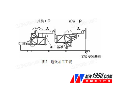
The anti-installation station selects the outer surface of the side beam as the installation reference (Z direction), and the bottom surface of the side beam is positioned as the Y direction, and the clamping point is selected to be close to the processing area to ensure sufficient clamping of the workpiece during processing and vibration reduction. Due to the limitation of the Z-direction of the device, the tooling cannot be too high, so the clamping arm is designed as a bending arm, and the pressing block is designed in a U shape and pressed on the two ribs respectively. The total length of the side beam is 22m. The aluminum alloy profile is soft and easy to deform. At the same time, the rib is thin and the machining vibration is very large. Therefore, the tooling adopts the unit module structure. The whole side beam is composed of 15 two types of modules, which are arranged in a straight line on the workbench. One clamping module is arranged at each end of the door frame, and a supporting module is arranged between the door frames. At the same time, in order to ensure the straightness of the workpiece, each tooling module is designed with a uniform installation reference, and is installed on the equipment working platform by using the positioning key.
Integrated Gear Pump,Electro-magnetic drive pump,Ceramic printing pump,CIJ inkjet printer pump,Electromagnetic metering Pump
Suzhou Macxi Fluid Technology Co.,Ltd. , https://www.macxipump.com