Here we will learn how to use Mastercam to analyze and design a workpiece and how to machine it on a CNC milling machine.
Mastercam is a CAD/CAM integrated system based on microcomputer platform, focusing on CNC machining programming. Its curve and surface design functions are for CNC machining programming. It has 2-5 coordinate CNC milling programming capability, wire cutting machining programming capability and turning. Machining programming capabilities are widely used in the mold manufacturing industry. This section introduces the use of Mastercam and the operation of CNC machine tools through an example.
The process of designing the workpiece dimensions of Figure 1 is as follows:
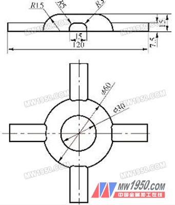
Figure 1 Parts drawing
1, geometric modeling
1) Click F file, W to open a new file in the main function area, and create a new file;
2) Click in the toolbar ![]() with
with ![]() , setting the viewing angle and the composition surface as top views;
, setting the viewing angle and the composition surface as top views;
3) Click C drawing, A arc, R point radius circle in the main function area, input the center point coordinate “0,0â€, radius “15â€, the result is shown in Figure 2;

figure 2
4) Click Z: 0.000 in the sub-function area and enter the Z-axis depth "-15";
5) Enter the coordinates of the center point “0,0†and the radius “30â€. The result is shown in Figure 3;
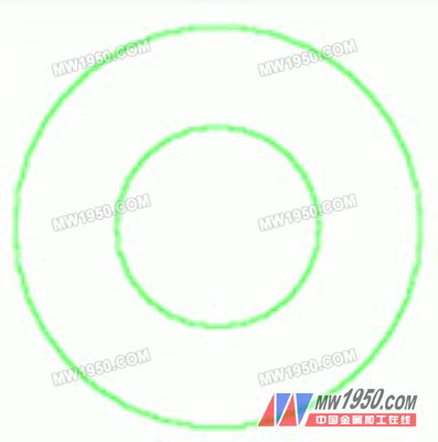
image 3
6) Click in the toolbar  with
with ![]() , the perspective is set to the front view, and the composition surface is set to the space drawing;
, the perspective is set to the front view, and the composition surface is set to the space drawing;
7) Click back to the main function table, click C drawing, A arc, E two-point arc in the main function area, grab the point with the grab point mode U, and enter the radius "15", as shown in Figure 4;

Figure 4
8) Click in the toolbar  with
with  , set the angle of view and the composition surface to the front view;
9) Click Z:-15.000 in the sub-function area and enter the Z-axis depth "60";
10) Click back to the main function table, click C drawing, R rectangle, C center point, input center point coordinates "0, -15", width "15", height "15", as shown in Figure 5;

Figure 5
11) Click back to the main function table, click M trimming, B interrupt, 2 break, and then break the two vertical edges of the rectangle at the midpoint;
Next page
Lap Joint Flanges (LJ Flanges) are used on piping fitted with lapped pipe or with lap joint stub ends the combined initial cost of the two items being approximately one-third higher than that of comparable Welding Neck Flanges.
Lap joint flange is having two components, a stub end, and a loose backing flange. Stub end is butt welded to the pipe and Backing flange freely move over the pipe. The backing flange can be of different material than stub material and normally of the carbon steel to save the cost. Lap flange is used where frequent dismantling is required, and space is constrained.
Furthermore, a standard lap joint flange will typically have a longer hub length in comparison to a slip on flange, but this is often considered unnecessary for many applications.
The lap joint flange is practically identical to a slip-on flange except it has a radius at the intersection of the bore and flange face.
Lapped Flange,Joint Flange,Lap Joint Flange,LJ Flange
Shandong Zhongnuo Heavy Industry Co.,Ltd. , https://www.zhongnuoflange.com